

Projects

Introduction of Sand-Based Filter Bricks or Permeable Pavement
Sand-based permeable material is made from desert aeolian sand as raw material, through micro-particle coating technology and aeolian sand interface
Modification technology, the surface of the aeolian sand is made into a hydrophilic or hydrophobic material, and then according to the type of product, as the main
Preliminary design of pilot project for the renovation of Hangxinjiayuan sponge community (reported for approval)
31
For aggregates, materials with water permeability are made by a sintering-free molding technique. Sand-based permeable materials including sand-based
Water brick, silica sand filter stone, sand-based permeable curb stone, silica sand well block, silica sand drain cover and other products.
The main performance indicators of sand-based permeable materials have the following four points:
( 1 ) Compressive strength: 30MPa , 40MPa , 50MPa , 60MPa ;
( 2 ) water permeability: ≥ 1.5mL / (min · cm 2 ) ;
( 3 ) Frost resistance: After 75 freeze-thaw cycles, the compressive strength loss rate is ≤ 20% ;
( 4 ) Wear resistance: the length of the grinding pit is ≤ 35mm .
Renovation of Community Branch Roads and Parking Lots
The current urban branch road is cement concrete pavement, and the parking lot is laid with grass bricks.
The permeable pavement was remodeled and 50 new parking spaces were added, totaling 257 parking spaces. Based on overall leisure
Resources, enhance space vitality, and improve the purpose of water resources recycling, 300mm ×
150mm × 65mm silica sand filter bricks, parking spaces are mainly used according to the location: I
Use 250mm × 190mm × 60mm T-shaped green grass bricks; Class II uses 200mm × 100mm ×
65mm silica sand permeable paving brick; Class III uses hot melt marking line. 1000mm on the edge of the road ×
300mm × 150mm granite open side stone and 500mm × 120mm × 150mm sand
Base Through the Horizontal Edge Stone Paving.
The design of the branch road and parking lot of the project area shall be in accordance with the “Code for Construction and Acceptance of Sand-Based Pervious Brick Project”.
( CECS244:2008 ) Designed to meet the needs of roadway and compression and bending resistance. Branch road and parking
The specific practice of the road surface is shown in Figure 6.3-3 .
Preliminary design of pilot project for the renovation of Hangxinjiayuan sponge community (reported for approval)
32
Figure 6.3-3 Renovation of the road of the community branch and parking lot
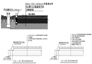
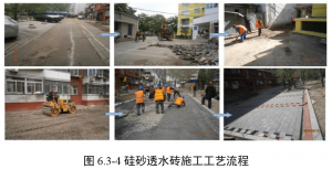
Figure 6.3-4 Construction process of silica sand permeable brick
After the tributary pavement and parking lot are paved with water, the height is 10.5cm , and the blind ditch and pebbles are set in the green space.
Side ditch. The rainwater from the branch road and the parking lot flows to the pebble side ditch, and then remits to the seepage well and finally enters the rainwater main pipe. effect
Figure 6.3-5 and Figure 6.3-6 .
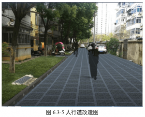
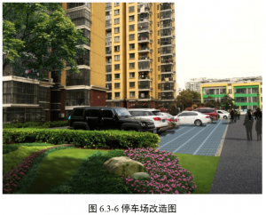
Figure 6.3-5 Sidewalk Reconstruction Diagram
Preliminary design of pilot project for the renovation of Hangxinjiayuan sponge community (reported for approval)
33
Greening the parking lot, guiding the vehicles to be neatly parked, and replanting greenery in places where greening is missing.
Dotted flower slopes and landscape stones. The transformation diagram is shown below:
Figure 6.3-6 Parking lot reconstruction
This design also upgrades and upgrades the non-motor vehicle lanes in the community. Add residential non-motorized parking
In order to transform the current temporary work shed into a non-motor vehicle parking garage, 296 non-motor vehicle parking spaces can be set .
Construction Process Design
This design and construction should follow the construction order of the first underground, the rear ground, and the deep to shallow construction, that is, the construction pipeline first.
Then carry out green planting and side stone installation, and finally complete the asphalt paving.
Low impact development facilities
Pebble side ditch
Laying 500mm × 300mm pebble side ditch in the green space of the residential area in the residential area , filling the gravel side ditch
0.2m thick charge φ 50 ~ 100 pebbles. The pebble side ditch can collect the rainwater that is disconnected from the downpipe, and at the same time
Play the role of energy dissipation and retention. Filtration and adsorption purification of pollutants by using biofilm attached to the pebbles
The function is to purify the rainwater at the beginning of the road and part of the green space, and reduce the initial rainwater pollution.
The total length of the pebble side trenches laid in the green space behind the house is about 1320m .
Preliminary design of pilot project for the renovation of Hangxinjiayuan sponge community (reported for approval)
34
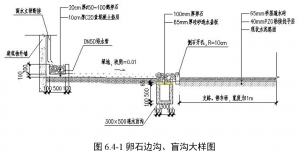
Water- Permeable Blind Ditch
A 300mm × 500mm permeable blind ditch is laid in the green space near the road side , and the cover is 6.5mm thick sand base.
Pervious brick, covered with 10cm thick pebbles. After the permeable pavement renovation, the community branch road, parking lot and square are infiltrated
The rainwater and the rainwater exceeding the permeability of the permeable bricks can all pass through the side of the opening to the blind ditch.
Figure 6.4-1 Pebble side ditch, blind ditch large sample
Water storage and reuse project
Rainwater Reservoir Design
Principle of rainwater purification
The water resources in Hefei City are in short supply, and the water pollution around the city is serious. The rain should be implemented as much as possible through engineering measures.
Resource utilization of water. 1 The roof rainwater in the community is disconnected by the rainwater riser and discharged to the pebbles on the outside of the building.
The side ditch also plays the role of energy dissipation and retention. Rainwater in the pebble trench can pass through rainwater pipes or through green fields.
It flows to the permeable blind ditch near the road side, where it also makes full use of the retention and infiltration of the green space behind the house.
2 The sand-permeable bricks are laid in the community branch road and the parking lot, and the rainwater in the infiltration part is sent to the slot of the current road surface.
In the water-permeable blind ditch, the surface rainwater exceeding the infiltration part passes through the open side stone discharge to the blind ditch. Completely through the surface
The drainage system collects rainwater, absorbs rainwater on the spot, relieves internal hemorrhoids, and effectively removes larger particles in rainwater.
Contaminants to reduce the filtration pressure of subsequent reservoirs.
In the front of the silica sand reservoir, a sand-sinking mud well can be set up to achieve initial sedimentation. Diversion and sedimentation
It is placed in the inspection well of the rainwater drainage pipe network in the community, so that the muddy sand in the turbulent state rainwater is trapped in the muddy sand.
In the well, the mud sand is reduced to the rainwater reservoir.
Preliminary design of pilot project for the renovation of Hangxinjiayuan sponge community (reported for approval)
35
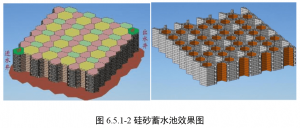
The outer wall of the reservoir is separated from the outside by a reinforced concrete structure. The honeycomb is placed in a honeycomb siliceous block.
The air block and the wall of the pool are filled with aerated blocks. The reservoir adopts a honeycomb structure, which can achieve stable structure.
According to the corresponding indicators, it can realize the simultaneous filtration and purification, anti-seepage and anti-evaporation integration, and ventilation and preservation.
The reservoir is designed with simulated stratum structure, and it is deeply filtered and biologically purified by sand-based filtration wells.
Now the rainwater purification function, the effluent COD , ammonia nitrogen and total phosphorus can reach the surface water quality standard of ClassIV . Silica sand storage
The structure of the pool structure and the water flow organization and the silica sand reservoir are shown in Figures 6.5-1 and 6.5-2, respectively.
Figure 6.5.11 Schematic diagram of silica sand reservoir structure and water flow organization
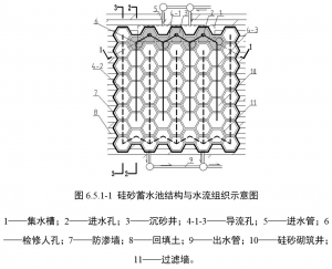
1– sump; 2 – inlet hole; 3 – Well sand; 4-1-3– diversion holes; 5 – inlet; 6
– repair manhole; 7 – seepage wall; 8 – backfill; 9 – outlet pipe; 10 – silica sand masonry;
11 – Filter wall.
Figure 6.5.1-2 Effect of silica sand reservoir
Preliminary design of pilot project for the renovation of Hangxinjiayuan sponge community (reported for approval)
36
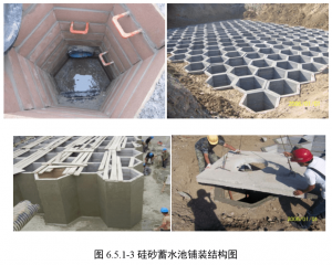
Figure 6.5.1-3 Silica sand reservoir paving structure diagram
We can provide DWG files for the design upon request.